
- Pioneer Pump Company
- Bosch Hydraulic Pump Komatsu Hydraulic Pump Linde Hydraulic Pump

Home> Technical Articles> Analysis on the routine maintenance and troubleshooting of centrifugal pumps
- Addressjinan,Shandong,China
- Factory Addressjinan,Shandong,China
- Worktime9:00-18:00
Analysis on the routine maintenance and troubleshooting of centrifugal pumps
NOVEMBER 02, 20221 Basic working principle of centrifugal pump
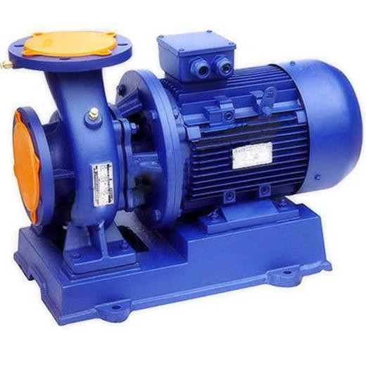
The centrifugal pump is designed according to the principle of centrifugal force. The driving motor drives the impeller to rotate by the pump shaft to generate centrifugal force. Under the action of centrifugal force, the liquid is raked along the blade flow path to the impeller outlet, collected by the pump body and sent to the discharge pipe, and the liquid is obtained from the impeller. The energy increases both static pressure and kinetic energy, pushing the liquid to the work site. When the impeller rotates, a negative pressure is formed at the center of the suction port, and a pressure difference is generated between the liquid reservoir and the liquid at the center of the impeller. Under the pressure difference, the liquid is continuously pressed into the suction port of the impeller, and then continuously It is thrown out to achieve continuous fluid transport.
2 The main components of the centrifugal pump
(1) Pump body: The shell of the single-stage pump is volute type, and the inner cavity is a spiral type liquid passage for collecting the liquid pumped out from the impeller and guiding it to the pump outlet, so that the kinetic energy is further changed. Static pressure energy.
(2) Impeller: The impeller is a work component. The impeller is fixed on the shaft by a key, and is driven by the motor to perform energy transfer conversion on the liquid work. According to the structure, it is divided into three types: closed type, open type and semi-open type. The closed impeller is more efficient and the open impeller is less efficient.
(3) Sealing ring: It is a sealing device installed between the impeller and the pump casing. By adjusting the gap between the two, the leakage amount is reduced. If the gap is too large, it will affect the flow of the pump, and the efficiency will decrease. If the gap is too small, the friction between the impeller and the pump casing will cause wear, increase the extra load, and cause the motor to overload and heat. It is preferred that the gap of the seal ring be maintained between 0.2 and 1.3 mm.
(4) Shaft and bearing: The main part of the pump shaft for transmitting energy, which rotates at high speed during operation and carries a large torque. The material is generally selected from carbon steel or alloy steel with high strength and is quenched and tempered.
The bearing is a member that supports the pump shaft on the pump shaft, and has two types of rolling bearings and sliding bearings. Common bearing lubrication methods are oil lubrication and grease lubrication.
(5) Shaft seal: The seal between the pump shaft and the front and rear end caps is called shaft seal, which mainly prevents the liquid leakage in the pump and the air from entering the pump to achieve the purpose of sealing and preventing the cavitation of the pump caused by the intake air. Shaft seals generally include: skeleton rubber seals, mechanical seals and packing seals.
3 Centrifugal pump daily maintenance
(1) Check the centrifugal pump piping and seals for leaks every shift. Turn the centrifugal pump shaft by hand before starting to see if the centrifugal pump is flexible.
(2) Observe that the oil level should be at 1/3-1/2 of the oil mark. The lubricating oil (fat) should be replenished daily according to the lack of oil and replaced once a month.
(3) For the centrifugal pump with the installation position higher than the liquid storage tank (tank), unscrew the water-conducting screw plug of the centrifugal pump body before opening the pump, and the water-priming device can start the equipment.
(4) When the centrifugal pump is running normally, open the outlet valve gradually, and observe the motor load and pipeline pressure. By adjusting the outlet valve, the flow rate and head are controlled as much as possible on the nameplate to ensure that the centrifugal pump operates at the highest efficiency point.
(5) During the operation of the centrifugal pump, the maximum temperature of the bearing shall not exceed 80 °C. If the bearing temperature exceeds 60 °C during operation, it shall be checked whether the lubricating oil level, the cooling water pipeline is intact and whether any foreign matter enters the tank.
(6) When the centrifugal pump is to be stopped, first close the outlet pants valve, pressure gauge, and then stop the motor.
(7) When the newly installed centrifugal pump starts to operate, change the lubricating oil (fat) after 100 hours, and then change the oil (fat) every 500 hours (or January).
(8) Regularly adjust the packing gland and replace the packing in time to ensure that the dripping in the packing chamber is normal (no more than 50 drops per minute), and the mechanical seal should ensure that the cooling water is normal.
(9) After the centrifugal pump stops in winter, it is necessary to unscrew the liquid screw plug in the lower part of the pump body to release the medium to prevent freezing cracking.
(10) The centrifugal pump should be completely deactivated for a long time. The pump should be completely dismantled and wiped dry. The rotating parts and joints should be greased and properly stored.
4 Centrifugal pump common fault analysis and treatment methods
4.1 Flow is too small
Causes and treatment methods:
(1) The liquid absorption is not smooth. If the outlet pressure is low, the current is much smaller. The pipeline before the pump, such as the suction pipe, leaks, the bottom valve leaks; the inlet is blocked; the bottom valve is not deep enough under the liquid; the suction liquid is difficult, affecting the flow. . Treatment method: check the suction pipe and the bottom valve to block the leakage source; clean the sludge or blockage at the inlet; the depth of the bottom valve must be greater than 1.5 times the diameter of the inlet pipe, and increase the depth of the bottom valve.
(2) The discharge pipe is clogged, mainly because the pressure is high and the flow rate is small, and most of the outlet pipes are blocked. Treatment: Check and clean the outlet pipe.
(3) The seal ring or impeller wears too much; the suction height is too high. Treatment: Replace the seal ring or impeller; Reduce the installation position of the pump, or replace the high lift centrifugal pump.
4.2 Motor overload trip
Causes and treatment methods:
(1) The pump (motor) spindle is bent and the pump spindle is not concentric with the motor spindle. Treatment: Correct the pump (motor) spindle or adjust the relative position of the pump to the motor.
(2) The selection of the centrifugal pump is not suitable. Treatment method: select the centrifugal pump with suitable head and flow.
(3) The foreign body in the pump body is blocked, and the motor or pump bearing box bearing is damaged. Treatment: Clean up the blockage; replace the motor or pump bearing housing bearing.
4.3 The pump body vibrates or produces noise
Causes and treatment methods:
(1) The centrifugal pump is installed too high to generate cavitation vibration. Treatment method: Reduce the installation height of the centrifugal pump.
(2) The motor or bearing housing bearing is damaged. Treatment: Replace the new bearing.
(3) The pump spindle is bent or not concentric with the motor shaft. Treatment: Correct the curved pump shaft or adjust the relative position of the pump to the motor.
4.4 Pump shaft or motor bearing overheating
Cause: Lack of lubricant (fat) or bearing damage. Treatment: Fill the lubricant (fat) or replace the bearing. When the pump is running normally, the bearing temperature should not exceed 80 °C. When it exceeds 60 °C, it should be found for the cause of the fault.
5 Common repair methods for major components
(1) Repair of impeller: Repair by surfacing or repair welding, mechanical processing after welding to achieve the desired accuracy, and finally dynamic balance test.
(2) Repair of the bushing. The amount of wear is small, and it is repaired by post-weld-turning. If the wear marks are deep, you should replace the new bushing.
(3) Repair of the pump shaft. When the amount of wear is not large, repair by the method of first surfacing and turning; when the wear amount is large, the repair can be carried out by the “inlaid part method”; when severe wear or crack occurs, the new shaft is replaced.
(4) Repair of the pump body. When the pump body is worn or cracks occur due to vibration, impact or knocking, repair is performed by “pre-welding or bonding and grinding”.
 Parker Piston Pump 400481005068 PV180R1K4T1N2LZ+PVAC2PCM
 USA VICKERS Pump PVM131ML10GS02AAC28200000A0A
 USA VICKERS Pump PVQ13-A2R-SE1S-20-CG-30-S2
 Japan Dakin original pump V38A4RX-95RC
 USA VICKERS Pump PVH131R13AF30B252000002001AB010A